Intro
Connection principles are common for all types of devices. No mater it is a wheel or joystick or rudder pedals. Schematic is identical. Exact location of specific pins vary depending on the actual board.
Warning!
NEWER, EVER, TRUST WIRE COLOR CODING!
Check name of the pin or wire coming from encoder and ALWAYS connect by the name, not by the color of the wire. There is no standard wiring color coding and each manufacturer can change the color of the wire without any notice. Match connections BY THE NAME!
Required connections
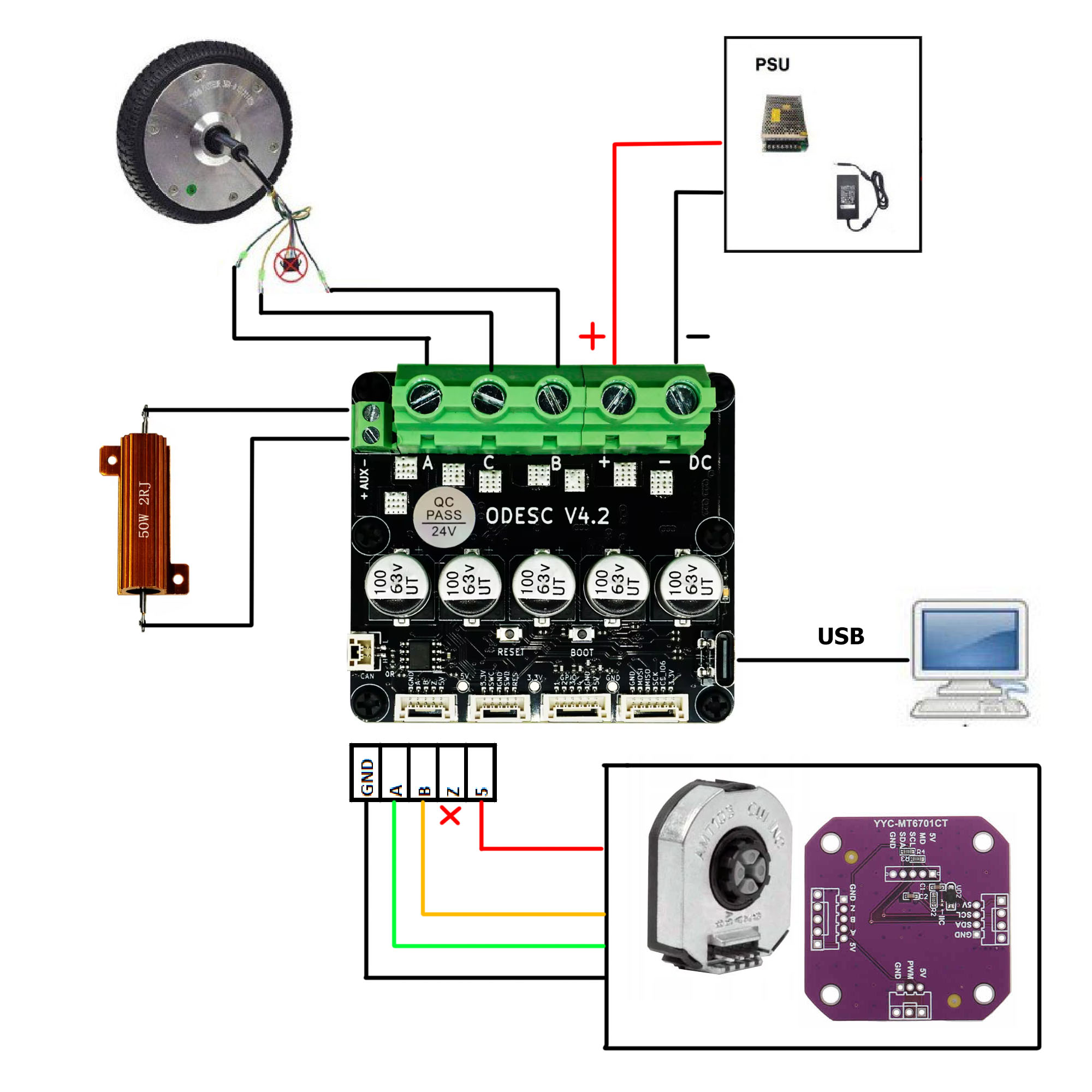
ODESC 4.2 (Single axis)
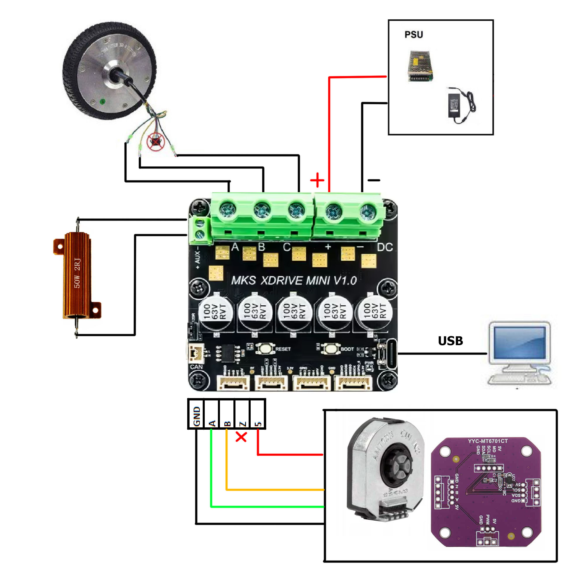
MKS XDRIVE MINI (Single axis)
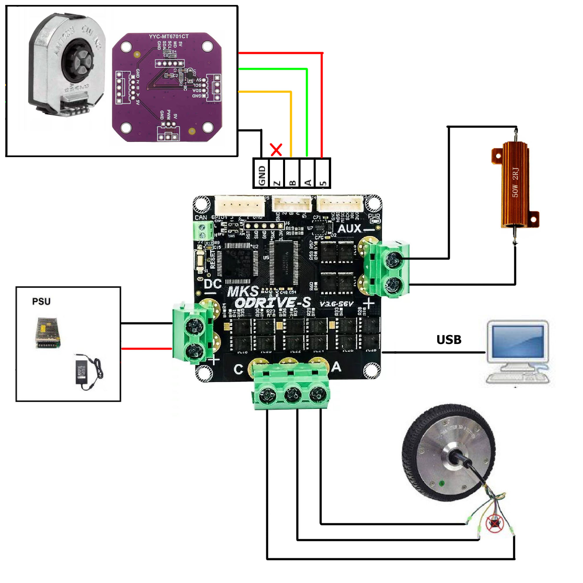
MKS XDRIVE-S (Single axis)
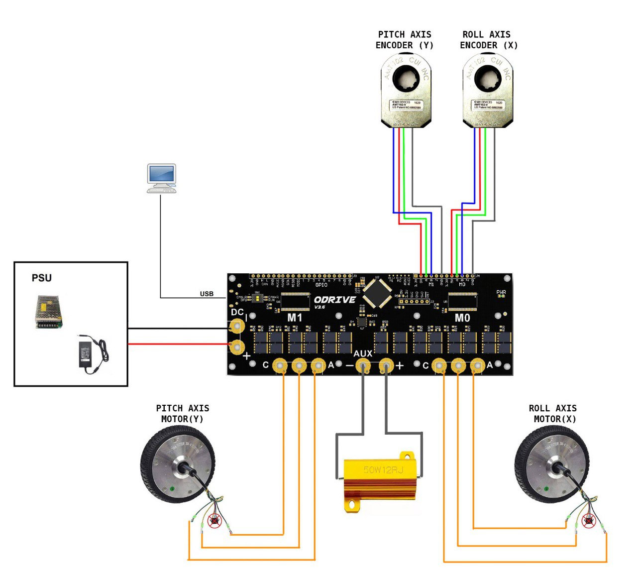
ODrive/XDrive (Dual axis)
Keep order of encoders and motors!
Both axis need to be connected as on the picture! Pitch to M1 and Roll to M0
Warning!
SECURE ODESC board need modification to work correctly. See note there!
Optional connections
Connecting additional axes (Analog sensors)
FFBeast firmware supports up to 3 additional analog sensors connected. Signal line must be connected to GPIO 1, 2 or 3. Locate corresponding pins depending on your exact board.
Use any of GND pin and power according to sensor datasheet (either 3.3V or 5V).
Analog mode need to be selected for corresponding GPIO in configurator in order to activate functionality!
STM32 controllers can read on analog input only range 0V - 3.3V. In case you use 5V sensor make sure that active range of it is the supported range. Signal values over 3.3V will be just clipped to 3.3V!
Connecting buttons
FFBeast firmware supports up to 8 separate buttons connected. Signal line must be connected to GPIO 1, 2, 3, 4, 5, 6, 7 or 8. Locate corresponding pins depending on your exact board.
Generic button mode need to be selected for corresponding GPIO in configurator in order to activate functionality!
As in button mode GPIO pins are pulled up internally, use GND pin as second side connection of your button!
If you need to connect more then 8 buttons, or your board do not have enough pins (ODESC, XDDRIVE MINI, XDRIVE-S do not have all gpio pins routed to connectors) consider using SPI extensions.
Connecting SPI extensions
FFBeast firmware supports connecting additional SPI extensions. Unfortunately shift registers in most cases actively drive MISO line and interfere with driver initialization. We can not connect it just to exposed on board SPI pins without proper tristate buffers. So to make things easier for SPI purpose we need to use normal GPIO pins as standard nCS, SCK and MISO lines.
In ODrive/XDrive schematic only pins 3,4,and 5 do not have additional filtering so those lines are recommended for connecting SPI extensions.
One of SPI extension modes must be selected and proper SPI GPIO pins assigned in configurator in order to activate functionality!
3xCD4021
This configuration is used in most of Thrustmaster wheel extensions. So use it when you want to connect TM wheel or have DIY shift registers board from mentioned shift registers.
Recommended connection:
- Connect GND line of extension to GND on ODrive.
- Connect MISO line of extension to GPIO 4 on ODrive.
- Connect SCK line of extension to GPIO 3 on ODrive.
- Connect nCS line of extension to GPIO 5 on ODrive (See comment below).
- Connect VCC line of extension to 3.3V on ODrive.
Recommended configuration on GPIO tab:
- Set SPI extension mode to 3xCD4201.
- Set GPIO mode for Pin 3 to SCK.
- Set GPIO mode for Pin 4 to MISO.
- Set GPIO mode for Pin 5 to nCS (See comment below).
Recommended configuration on Buttons tab:
- Set Button mode for all buttons in Shift register groups to Normal.
Some boards do not have Pin 5 exposed on board. In that case use any free GPIO pin for connecting nCS line. Remember to set nCS mode for corresponding pin you in configurator!
3xSN74hc165
There is support of extension board that you can purchase on Aliexpress.
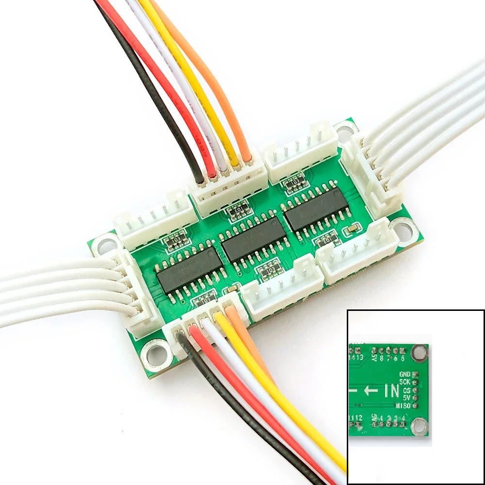
Marking on those boards is wrong! OUT side is for connecting other boards in chain. IN side is for connecting to microcontroller. Connect IN side to the ODrive!
Recommended connection:
- Connect GND line of extension to GND on ODrive.
- Connect MISO line of extension to GPIO 4 on ODrive.
- Connect SCK line of extension to GPIO 3 on ODrive.
- Connect nCS line of extension to GPIO 5 on ODrive (See comment below).
- Connect 5V line of extension to 3.3V on ODrive (Despite what is written on board it works better with 3.3V power).
Recommended configuration on GPIO tab:
- Set SPI extension mode to 3xSN74hc165.
- Set GPIO mode for Pin 3 to SCK.
- Set GPIO mode for Pin 4 to MISO.
- Set GPIO mode for Pin 5 to nCS (See comment below).
Recommended configuration on Buttons tab:
- Set Button mode for all buttons in Shift register groups to Normal.
Some boards do not have Pin 5 exposed on board. In that case use any free GPIO pin for connecting nCS line. Remember to set nCS mode for corresponding pin you in configurator!
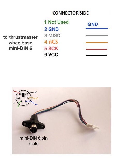
Thrustmaster grips
Thrustmaster grip extensions are supported natively.
Connection diagram:
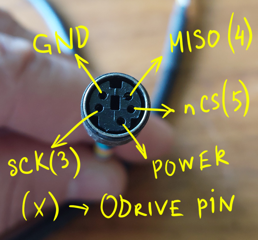
Recommended connection:
- Connect GND line of extension to GND on ODrive.
- Connect MISO line of extension to GPIO 4 on ODrive.
- Connect SCK line of extension to GPIO 3 on ODrive.
- Connect nCS line of extension to GPIO 5 on ODrive.
- Connect POWER line of extension to 3.3V or 5V on ODrive (TM grips work both from 3.3v and 5v power.).
Recommended configuration on GPIO tab:
- Set SPI extension mode to Thrustmaster.
- Set GPIO mode for Pin 3 to SCK.
- Set GPIO mode for Pin 4 to MISO.
- Set GPIO mode for Pin 5 to nCS.
Recommended configuration on Buttons tab:
- No additional configuration needed on button tab. All settings there are ignored when TM extension is selected
VPC grips (WIP)
VPC grips are in WIP stage so some functionality can be missing at the moment. Connection diagram:
Recommended connection:
- Connect GND line of extension to GND on ODrive.
- Connect MISO line of extension to GPIO 4 on ODrive.
- Connect SCK line of extension to GPIO 3 on ODrive.
- Connect nCS line of extension to GPIO 5 on ODrive.
- Connect POWER line of extension to 5V on ODrive.
VPC grips require 5V and will not work from 3.3V!
VPC grips work stable if pins 3, 4, 5 are used for communication. Connect signal wires as recommended!
Recommended configuration on GPIO tab:
- Set SPI extension mode to one of VPC modes.
- Set GPIO mode for Pin 3 to SCK.
- Set GPIO mode for Pin 4 to MISO.
- Set GPIO mode for Pin 5 to nCS.
Recommended configuration on Buttons tab:
- No additional configuration needed on button tab. All settings there are ignored when VPC extension is selected